Report
Group: 2
Section: 6
Wojciech Bieniek
Patryk Piwowarczyk
Aleksandra Szpiech
Ex. 4
Tutor name: Damian Grzechca
Simulation responses
After setting initial variables such as frequency and amplitude we tested all three circuit configurations. Following are observations of coil powered by switching DC source without and with overvoltage protection
Unprotected coil
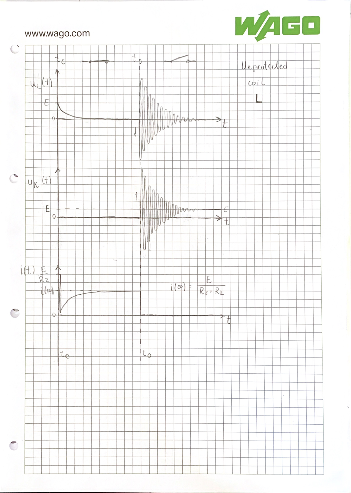
Observed responses for RL circuit with no overvoltage protection.
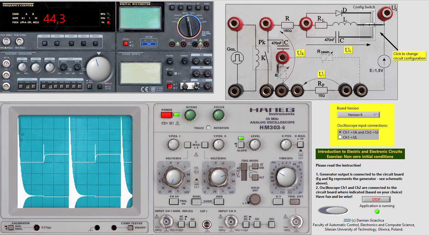
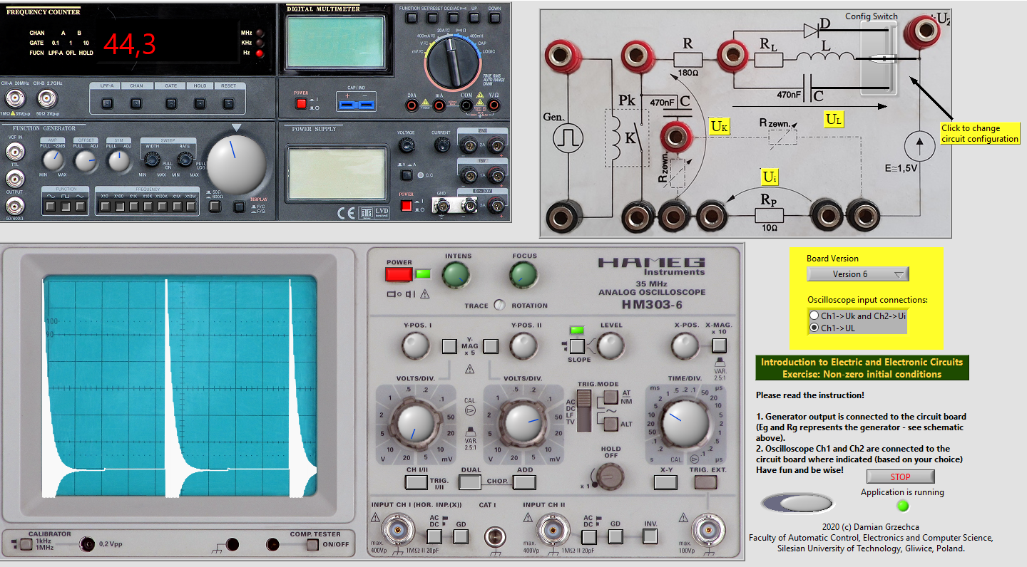
Characteristic of non-protected RL circuit
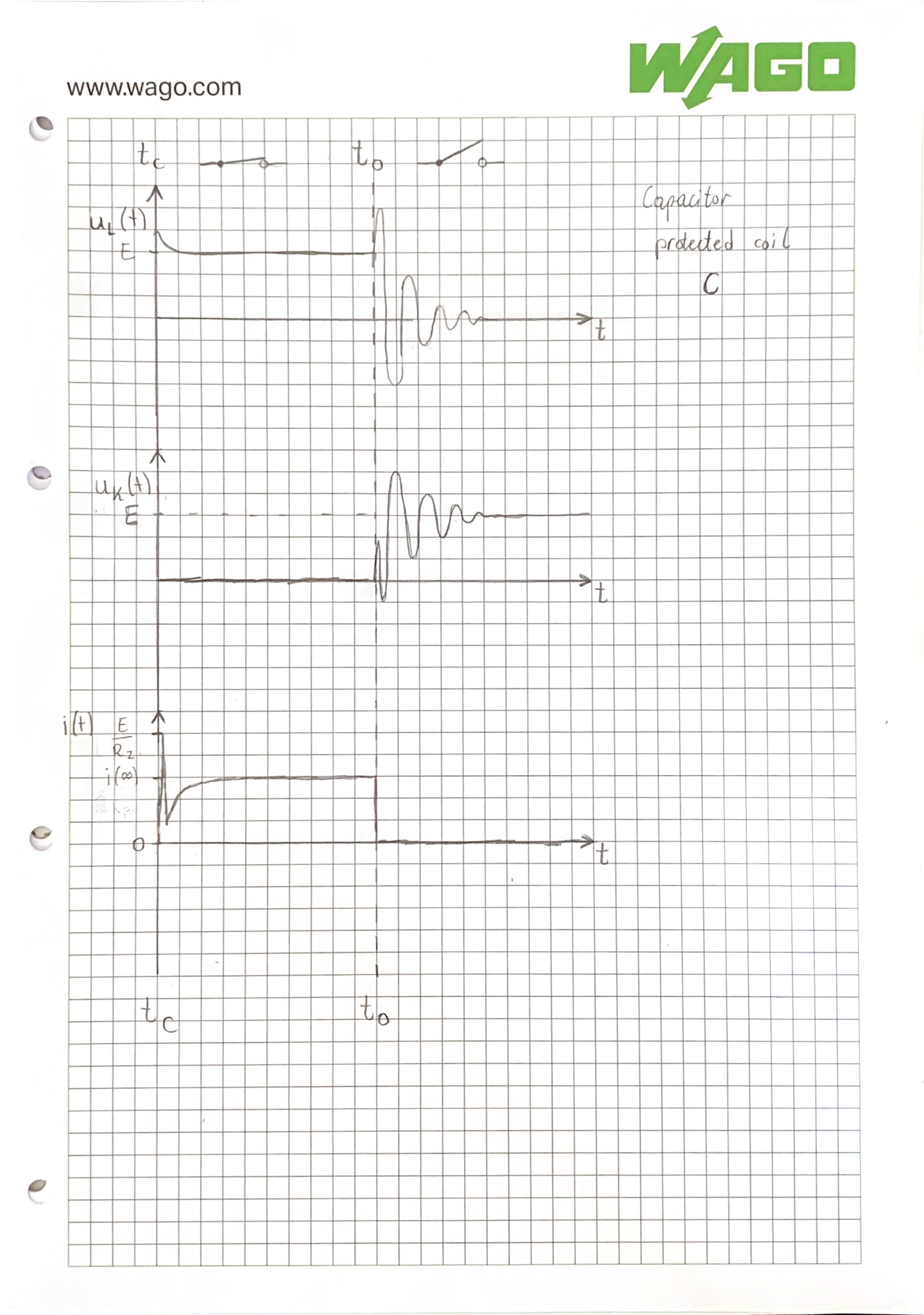
Capacitor protected
Observed responses for RL circuit with parallel capacitor.
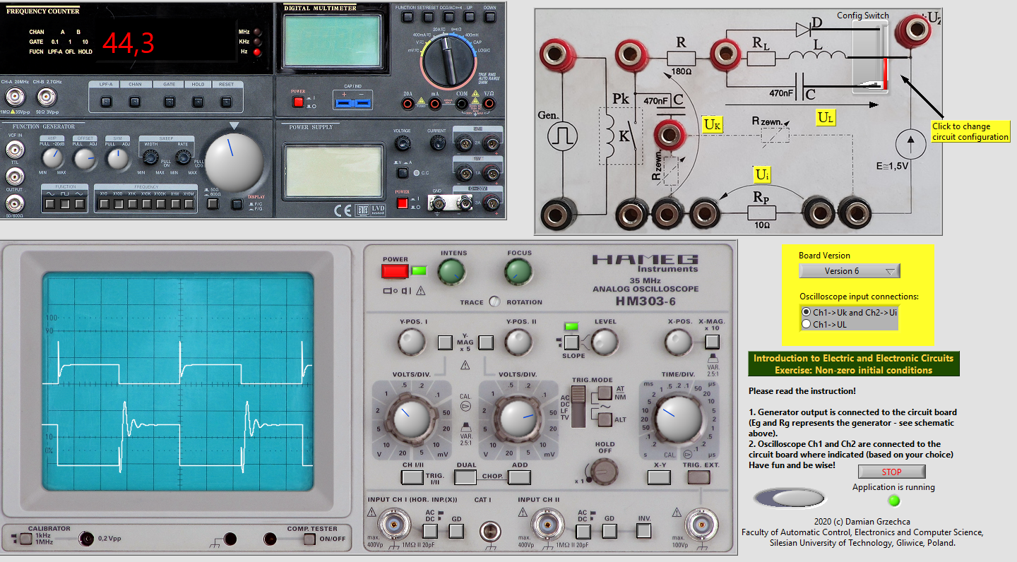
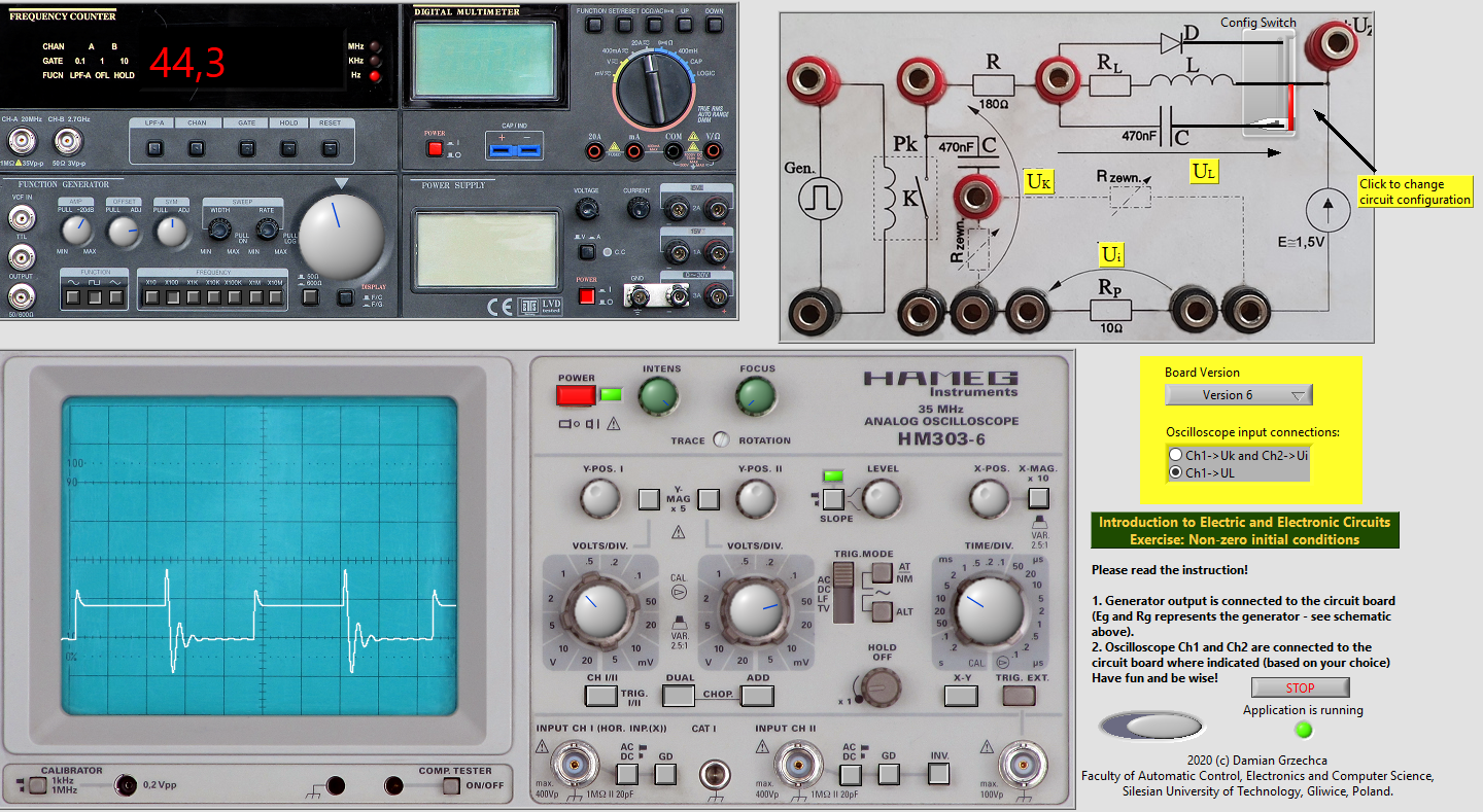
Characteristic of capacitor protected RL circuit
Diode protected
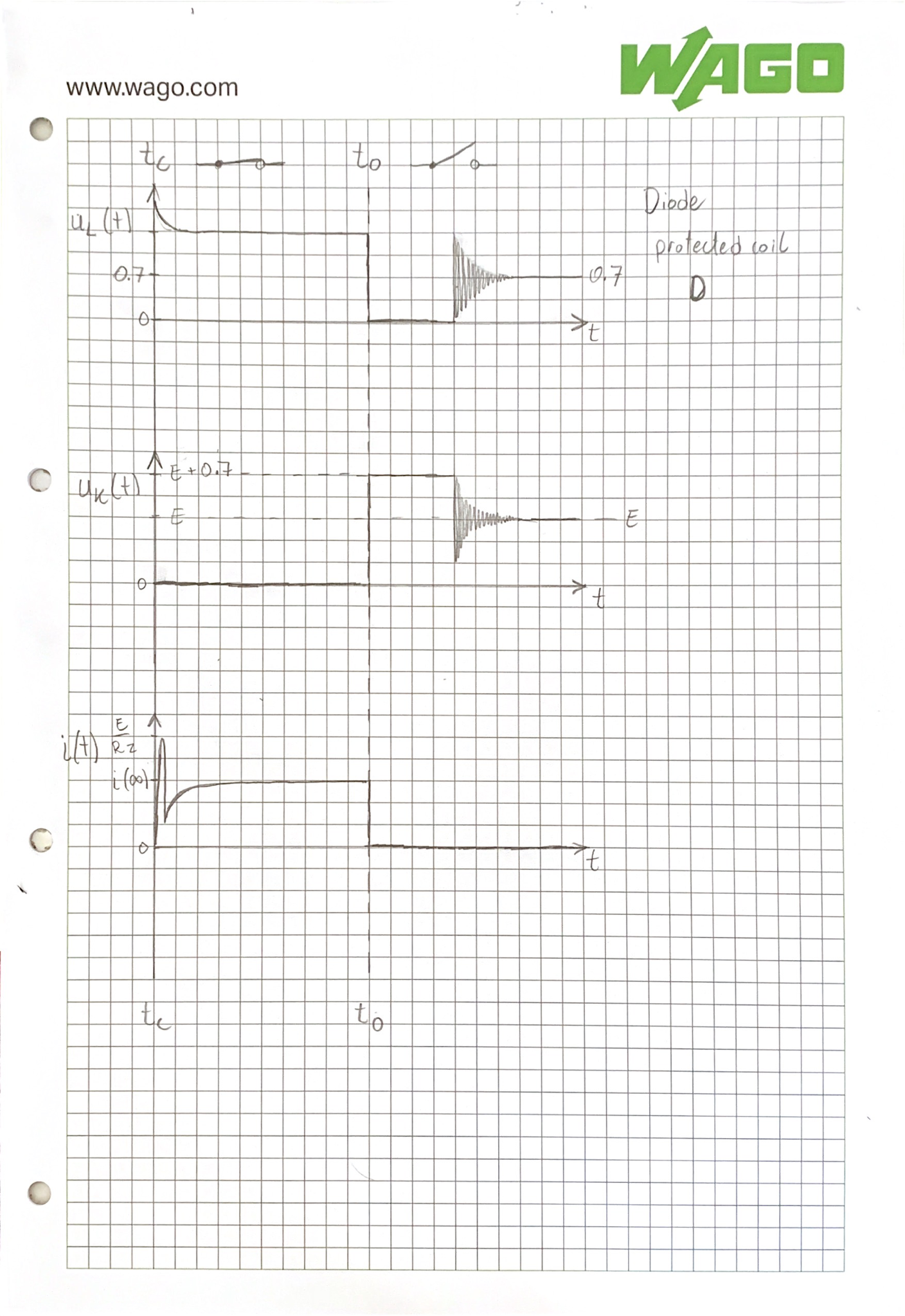
Observed responses for RL circuit with parallel diode.
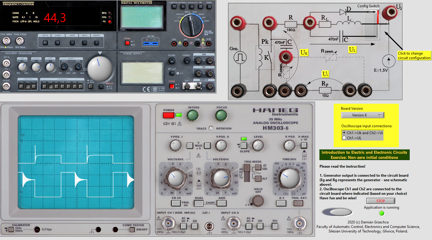
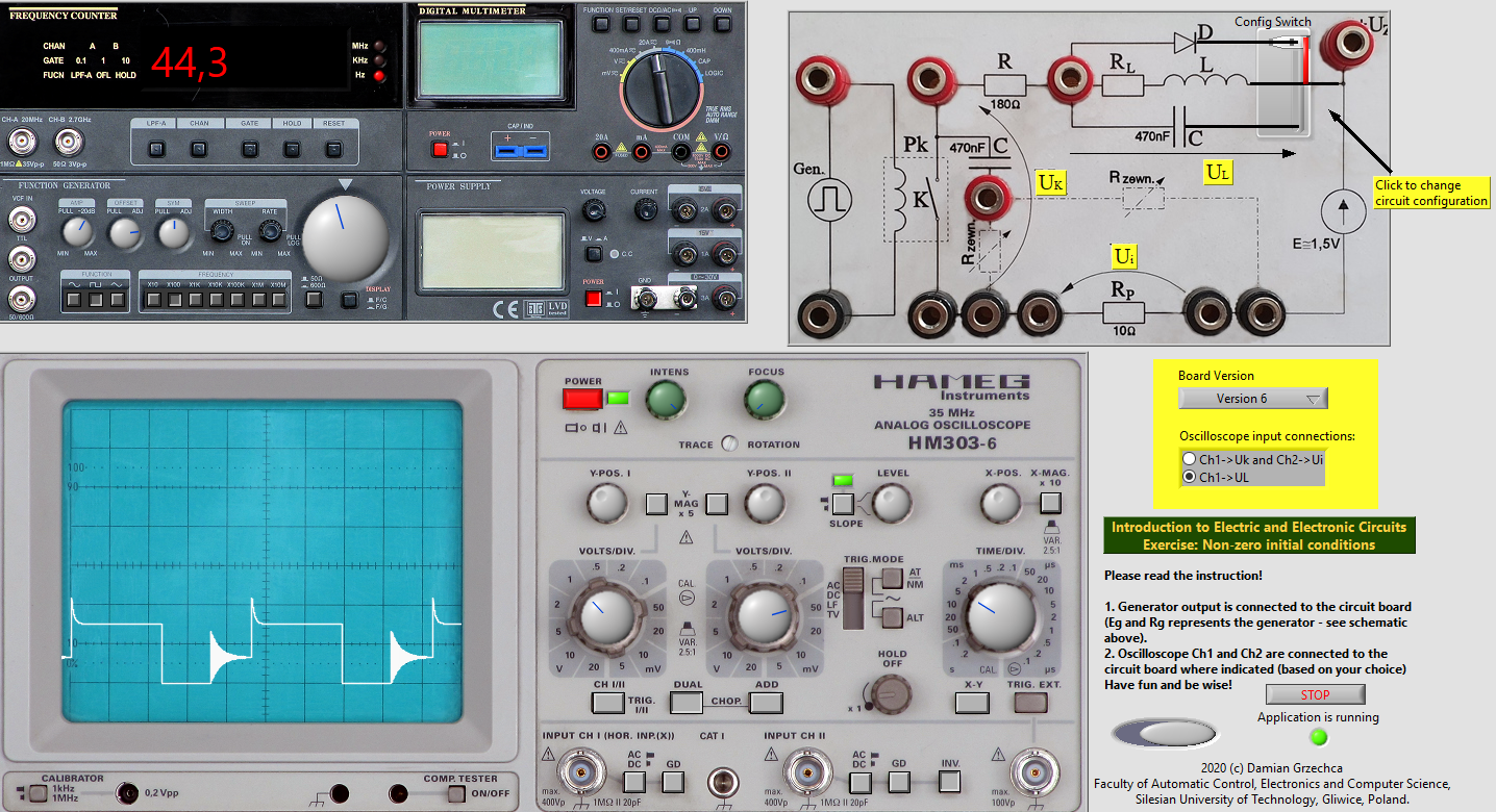
Characteristic of diode protected RL circuit
Data
Offset
| Circuit configuration | Unprotected | Capacitor | Diode |
|---|---|---|---|
| Oscilation period | — | ||
| Overvoltage value |
Observations description
In this RL circuit we observe the following behaviours, unexpected in an ideal circuit, yet apparent in all real coils.
Current spike
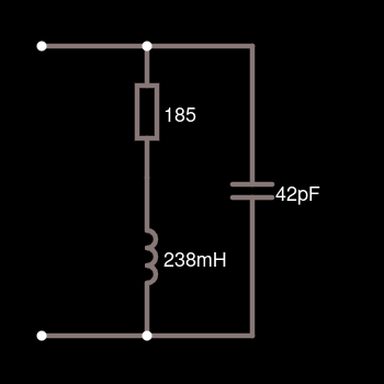
When the relay is closed, coil’s shunt capacitance acts as a short circuit, skipping coils internal resistance. Therefore the current spike reaches a value of .
Overvoltage ratio
For an unprotected coil the firtst oscilation period voltage on switch opening reaches 100 times the source value.
This value, as well as the oscillation frequency is decreased by a parallel capacitor to 2.4V, reaching 1.6 times the source value.
The most reliable high voltage protection is provided by a parallel diode, as the voltage drop over it cannot exceed 0.7V. Therefore the ratio is times the source voltage.
Coil properties
Real coil model
Conclusions
Coil can be used to generate 100 times the source voltage, which can be used for creating high voltage impulses.
If we however choose to use different properties of the coil, to which this behaviour might be harmful, we can protect our circuits from voltage spikes by using capacitors or diodes. Both have their advantages.
Capacitors have oscillating transition to the steady state, and can produce negative voltage, however if the capacitance is picked correctly, it can be smoother. Where capacitor protection excells is keeping the steady state flat.
Diodes on the other hand have perfect transition from to , however oscillations on them do appear later, when transitioning from to . Those oscillations are of much higher frequency than on an unprotected coil. Such behaviour could in some situations affect other parts of the circuit.