Report
Group: MK2
Section: 6
Aleksandra Szpiech
Patryk Piwowarczyk
Wojciech Bieniek
Ex. 2
Transient in the first order circuits with zero initial conditions switched on a DC source.
Tutor Name: dr hab. inż. Damian Grzechca
Board Number: 6
-
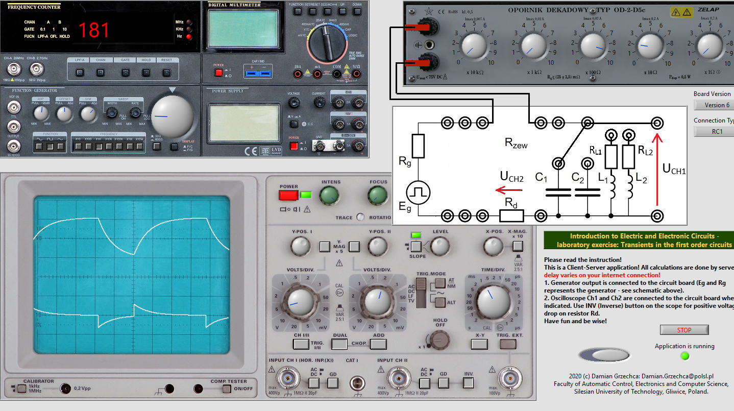
C1=749nF
- Radd3=920Ω
CH I: 5divV
CH II: 0.2divV
Time: 1divms
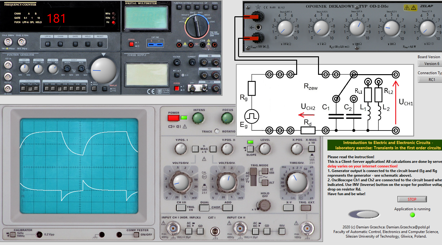
- Radd2=620Ω
CH I: 5divV
CH II: 0.2divV
Time: 1divms
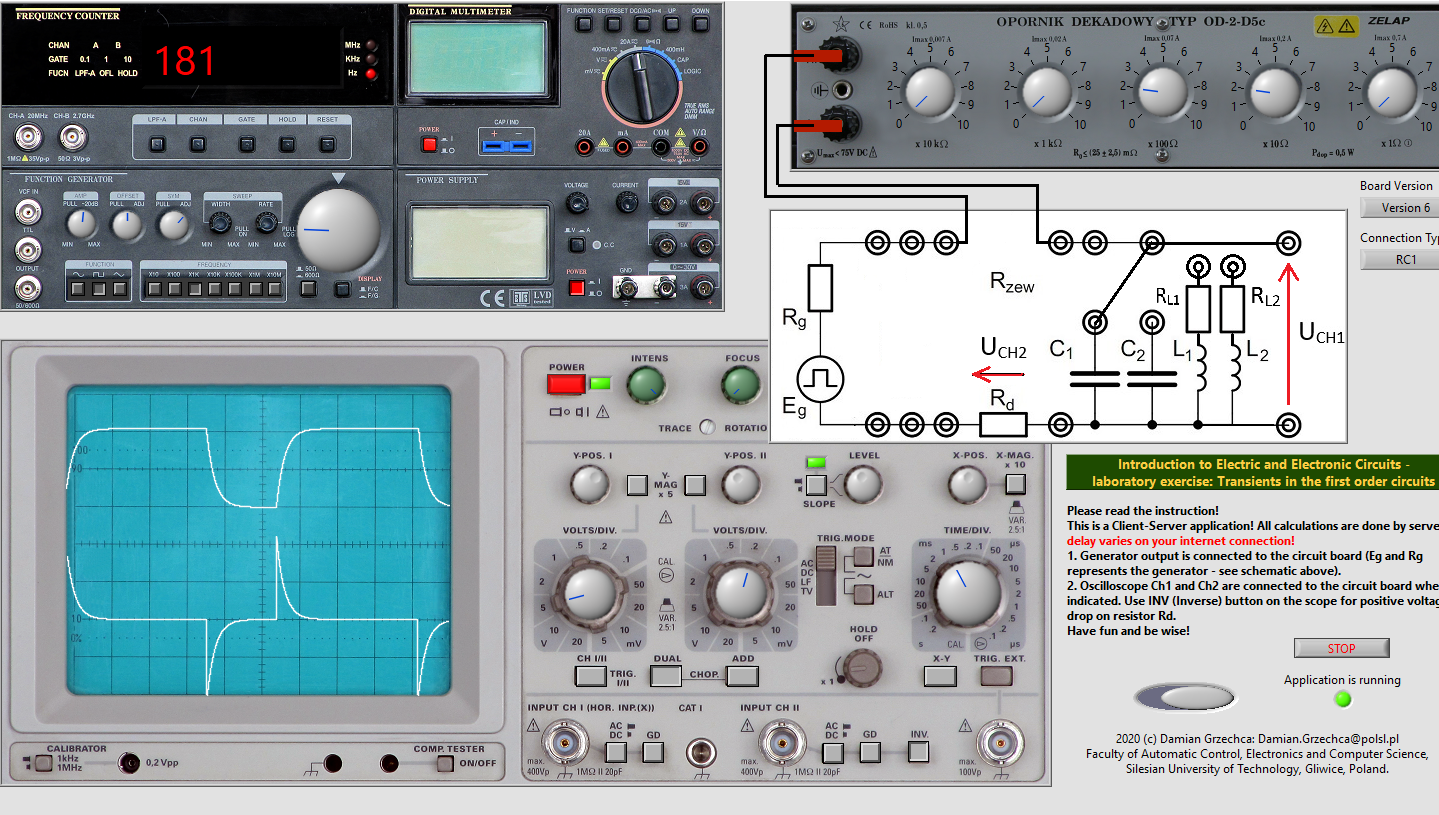
- Radd1=220Ω
CH I: 5divV
CH II: 0.2divV
Time: 1divms
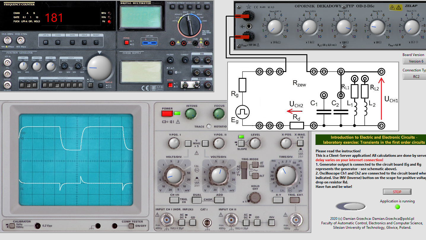
-
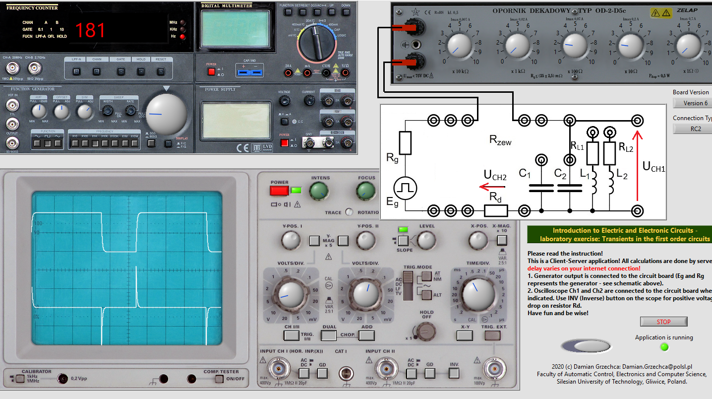
C2=149nF
- Radd3=920Ω
CH I: 5divV
CH II: 0.2divV
Time: 1divms
- Radd2=620Ω
CH I: 5divV
CH II: 0.2divV
Time: 1divms
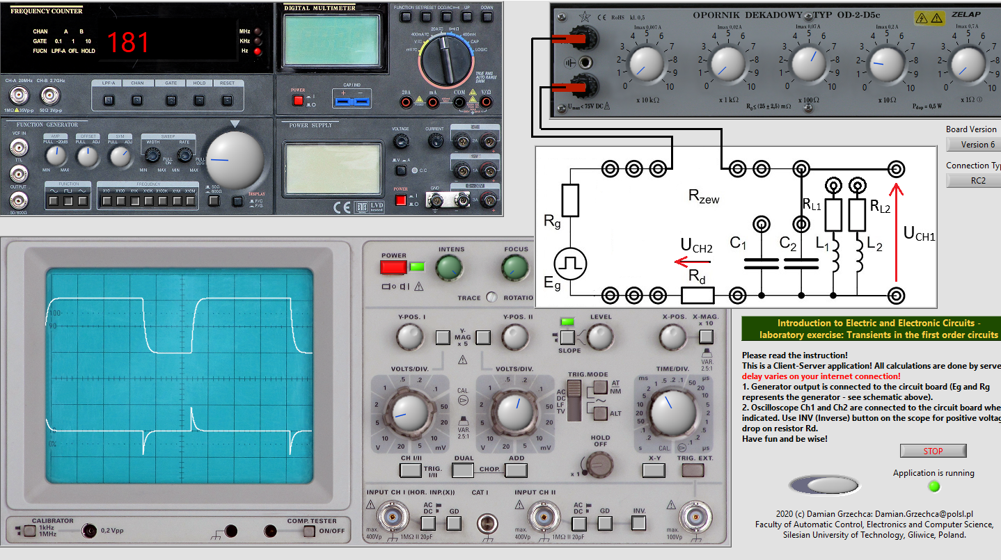
- Radd1=220Ω
CH I: 5divV
CH II: 0.2divV
Time: 1divms
-
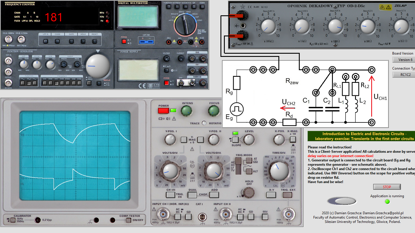
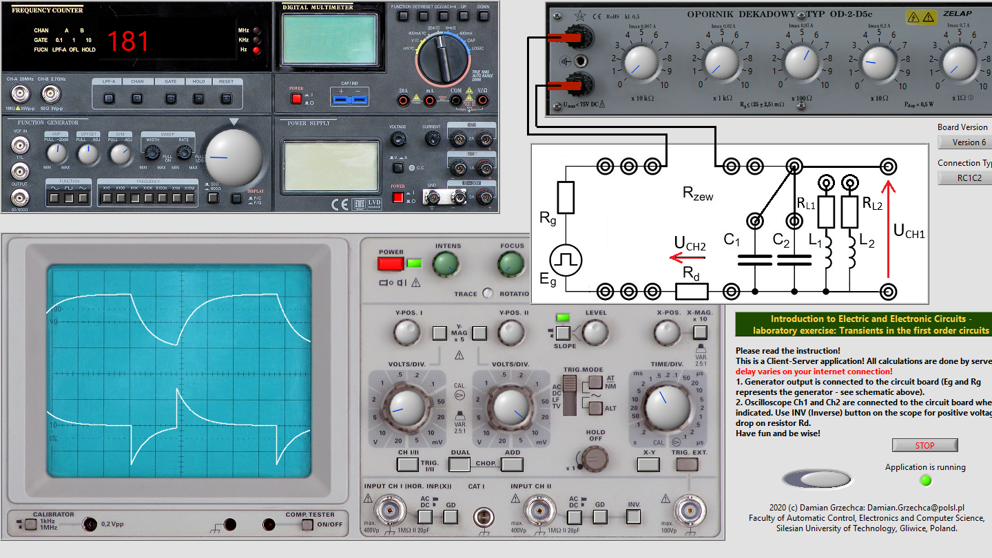
C1∣∣C2=898nF
- Radd3=920Ω
CH I: 5divV
CH II: 10divmV
Time: 1divms
- Radd2=620Ω
CH I: 5divV
CH II: 10divmV
Time: 1divms
- Radd1=220Ω
CH I: 5divV
CH II: 20divmV
Time: 1divms
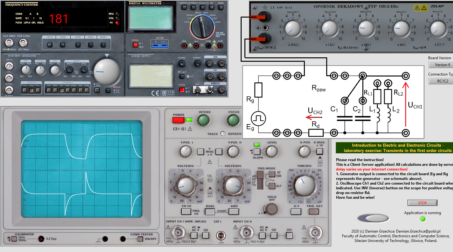
-
L1=130mH
- Radd3=920Ω
CH I: 10divV
CH II: 0.1divV
Time: 1divms
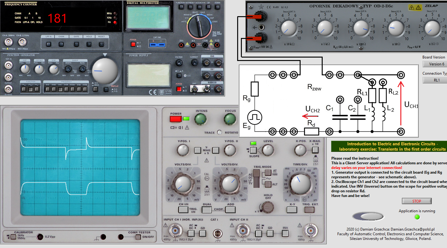
- Radd2=620Ω
CH I: 10divV
CH II: 0.1divV
Time: 1divms
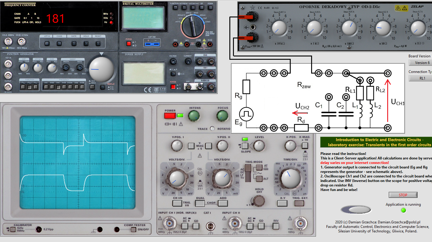
- Radd1=220Ω
CH I: 10divV
CH II: 0.1divV
Time: 1divms
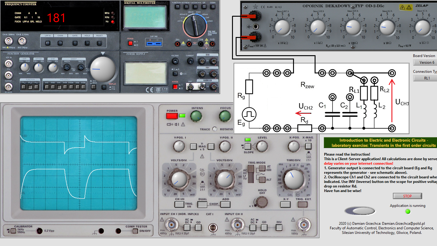
-
L2=34mH
- Radd3=920Ω
CH I: 10divV
CH II: 0.1divV
Time: 1divms
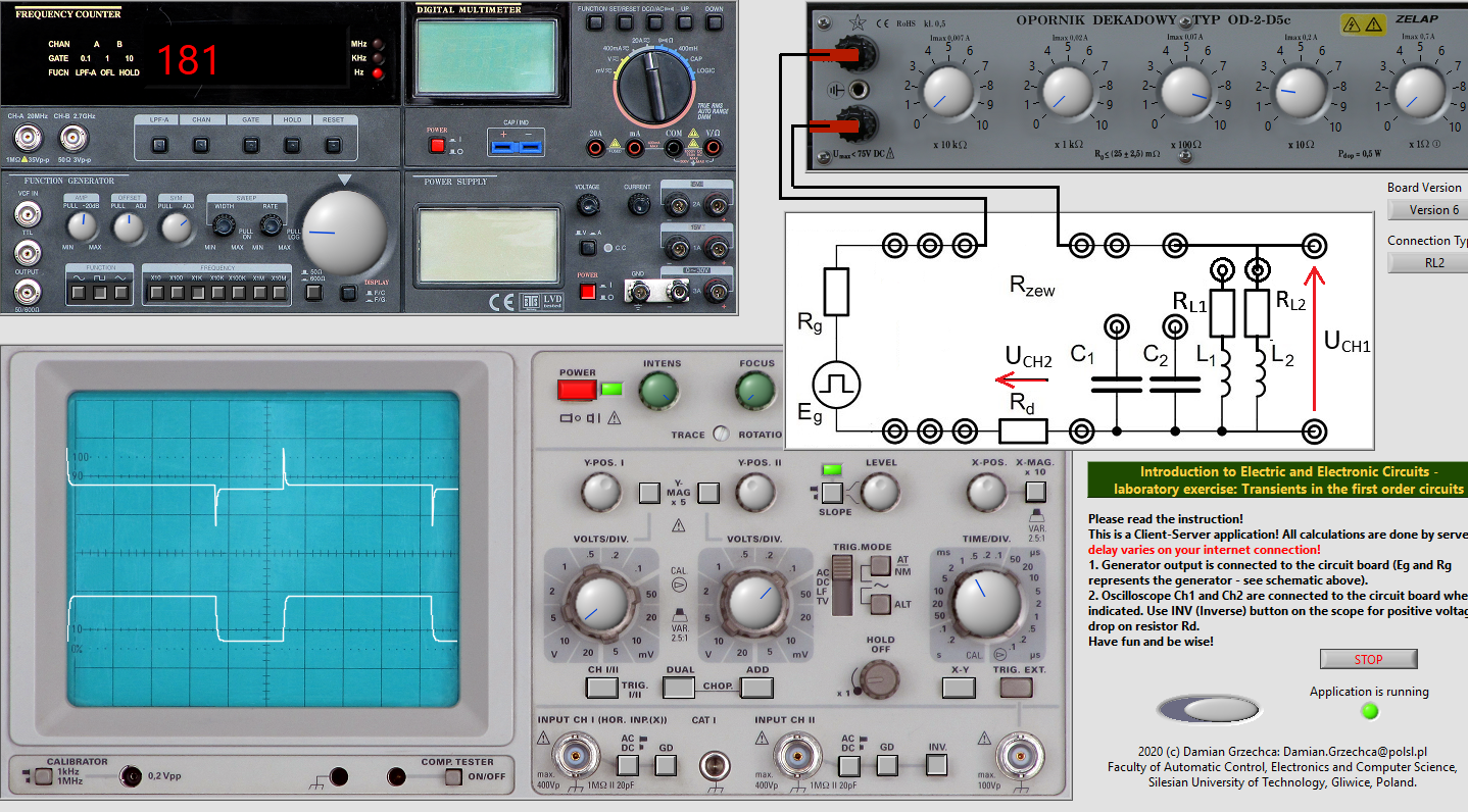
- Radd2=620Ω
CH I: 10divV
CH II: 0.1divV
Time: 1divms
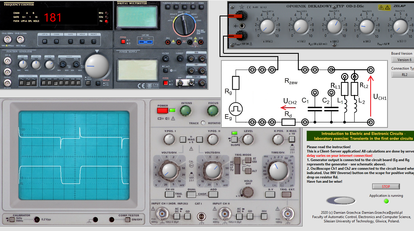
- Radd1=220Ω
CH I: 10divV
CH II: 0.1divV
Time: 1divms
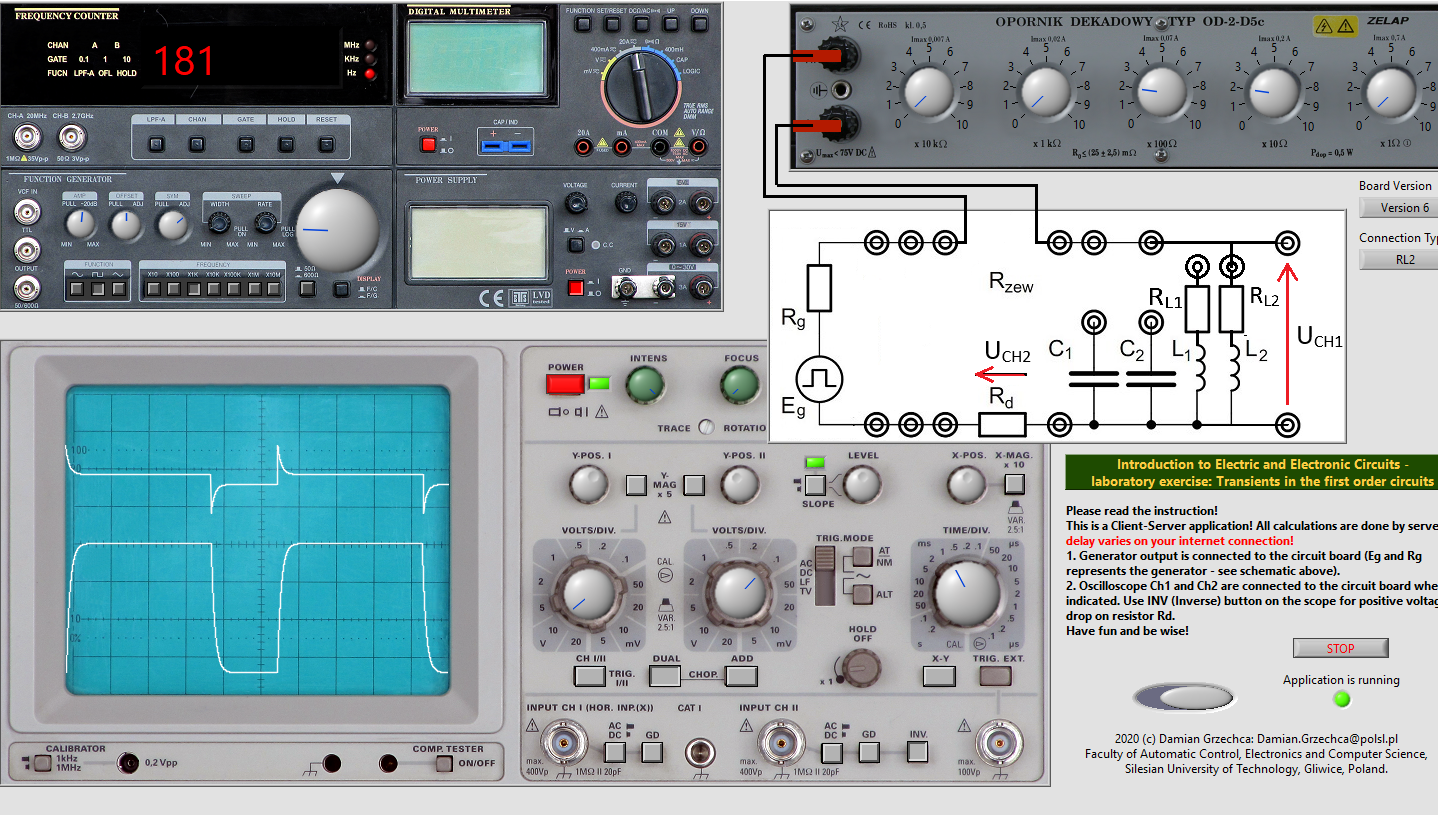
Here, the time constant values were calculated with formula τ=R∗C.
-
C1=749nF

-
C2=149nF

-
C1∣∣C2=898nF

| Capacitance |
C1=749nF |
C2=149nF |
C1∥C2=898nF |
| Resistance |
Radd1=220Ω |
Radd2=620Ω |
Radd3=920Ω |
|
Radd1 |
Radd2 |
Radd3 |
Radd1 |
Radd2 |
Radd3 |
Radd1 |
Radd2 |
Radd3 |
| U(0−)[V] |
0 |
0 |
0 |
0 |
0 |
0 |
0 |
0 |
0 |
| U(0+)[V] |
0 |
0 |
0 |
0 |
0 |
0 |
0 |
0 |
0 |
| U(∞)[V] |
2.2 |
2.2 |
2.2 |
2.2 |
2.2 |
2.2 |
2.2 |
2.2 |
2.2 |
| T[μs] |
164 |
464 |
689 |
32 |
92 |
137 |
197 |
556 |
826 |
| I(0−)[mA] |
0 |
0 |
0 |
0 |
0 |
0 |
0 |
0 |
0 |
| I(0+)[mA] |
15 |
6 |
4 |
15 |
6 |
4 |
15 |
6 |
4 |
| I(∞)[mA] |
0 |
0 |
0 |
0 |
0 |
0 |
0 |
0 |
0 |
| Inductance |
L1=130mH |
L2=34mH |
| Resistance |
Radd1=220Ω |
Radd2=620Ω |
Radd3=920Ω |
|
Radd1 |
Radd2 |
Radd3 |
Radd1 |
Radd2 |
Radd3 |
| U(0−)[V] |
0 |
0 |
0 |
0 |
0 |
0 |
| U(0+)[V] |
0 |
0 |
0 |
0 |
0 |
0 |
| U(∞)[V] |
2.2 |
2.2 |
2.2 |
2.2 |
2.2 |
2.2 |
| T[μs] |
590.9 |
209.6 |
141.3 |
154.5 |
54.8 |
36.9 |
| I(0−)[mA] |
0 |
0 |
0 |
0 |
0 |
0 |
| I(0+)[mA] |
0 |
0 |
0 |
0 |
0 |
0 |
| I(∞)[mA] |
21.66 |
11.66 |
8.33 |
28.33 |
15 |
10 |
Influence of R, C and L on τ
R - resistance [Ω]C - capacitance [nF]L - inductance [mH]τ - time constant [μs]
Increasing resistance prolongs the time constant for capacitors. It is so, because the capacitor charges with lesser current.
However, it’s increase shortens the time constant for inductors. The reason is, that the greater Thevenin resistance consumes energy stored in the coil faster.
Increasing capacitance prolongs the time constant for capacitors, as the capacitor accepts more charge.
Increasing inductance prolongs the time constant for coils, because they can store more energy.
i(∞)=iRd(∞)=RduRd(∞)=50[mV]/12Ω=4.17[mA]
RL1=iuL1=i(∞)uL1(∞)=4.17[mA]0.9[V]=215.8[Ω]
RL2=iuL2=i(∞)uL2(∞)=4.17[mA]0.44[V]=105.5[Ω]
We have observed the basic properties of RC and RL circuits. The relations between the 3 variable parameters: resistance, capacitance, inductance and the time constant are clearly visible on the measurements. Conducting a 3rd party simulation has proven that our plots are indeed of correct shape, albeit of different amplitudes and frequencies. The relations however remained, therefore we have confirmed the time constant equations τ=RC and τ=RL.
Conducting laboratories in distant learning form has proven to be much better solution for writing the report. We could prepare it the same time as conducting the measurements, which allowed us to avoid mistakes with notation, as well as loosing data. Repeating the same work on paper after a week, on the other hand, was not a very pleasant experience.


